GRID - Every Robot's AI Team
A General Robot Intelligence Development platform that enables seamless, end-to-end Robot AI development.
GRID provides seamless access to:
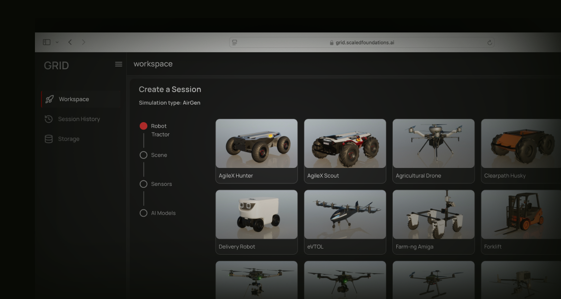
High-Fidelity Simulation
Run high-fidelity simulations with a variety of simulators such as AirGen and Isaac Sim. Import your own robots, or entire 3D scenes through Gaussian splatting. Leverage Unreal Engine 5 or Omniverse for scalable and performant data generation, policy training, and domain randomization - either in the cloud or on-prem.
Generate and Augment Data at Scale
Generate domain-rich datasets at scale for your form factor of choice - by bringing in realistic objects, equipping a variety of sensors, and varying weather and other environmental conditions. Parallelize over multiple machines, capturing camera, LiDAR, as well as rich ground truth for comprehensive robot training data.
Access AI Models
Invoke state-of-the-art AI models with just a few lines of code to create complex skills for your robots. Train or fine-tune your own, leveraging built-in autonomy stacks for mapping, planning, and trajectory generation. Chain multiple models for complex tasks, track performance across a variety of scenarios, and streamline iteration until your solution is fully deployment-ready.
Deployment Pipeline
Seamlessly deploy into robots with native support for industry standard protocols like ROS2, MAVLINK, and more. Efficient middleware techniques and cloud-centric workflows enable dynamic orchestration and effortless scalability.
Choose your GRID experience:
Open GRID
Web-based platform to deploy, train, validate and deploy intelligent robots
GRID Enterprise
Packaged GRID for a scalable, customizable and private GRID experience.
Get Started
Was this page helpful?